TFE4141: Design of Digital Systems 1
FPGA
VHDL
Object classes and Data types
- Object classes
- Constants
- Permanently defined value
- Signals
- Values change after a delay ∆ or an explicitly declared delay
- Variables
- Values change immediately (no ∆)
- Creates a Flip-Flop if read before it's written to. Otherwise it is optimized away.
-
Files
- Longterm storage of data
- Loaded when the model is run
- Write to files to store results from simulations
-
Predefined types
- std_logic(_vector)
- Signed / Unsigned
- Integer / Natural
- Real
-
Physical types (Time)
-
Custom types
- Syntax: type T_MY_TYPE is (val_1, val_2, val_3)
Logic
Combinational logic
Sequential logic
Concurrent code
Sequential code
Finite State Machine (FSM)
Mealy machine
FSM whose output values are determined both by its current state and the current inputs.
Moore machine
FSM whose output values are determined solely by its current state.
Time and simulations
Latches
Synthesis
Microarchitecture and Block diagrams
Design process
«How do we efficiently design a digital system of the desired quality, that meets the customer needs?»
Design:
- Capture requirements
- Write specification
- Model
- Write code
- Verify
- Implement (synthesis+place+route+floor plan)
- Validate
- Manufacture
- Test
Desired quality:
- Verification metrics: Code coverage, functional coverage, pass rate
- Formal verification
- Code standards followed
- Code reviews done
Efficiently:
- Cost effective
- With high return on the investments
Customer needs:
- Requiremens must be met.
- Validation ensures that the product actually satisfy the customer needs.
Low power design techniques
Power usage in an FPGA is divided into two part, static and dynamic.
Dynamic Power/Energy
The dynamic energy consumed by an FPGA is the energy consumed as a consequence of tranisistors switching state (
The dynamic power is found by using:
Here "a" is the activity factor and f is the switching frequency.
Lowering the clock rate reduces dynamic power usage, but it will not reduce the dynamic energy needed for a task requiring N transitions. As the task takes longer it will use more static energy and therefore increase the total energy needed for the aforementioned task. See "Race to Halt"
Static Power/Energy
The static energy is the energy consumed by the FPGA even if no transistors change state. This consumption is mainly due to transistor leakage. The static power can be found from the following equation:
Reduction Techniques
The following subsections describe different ways of reducing dynamic or static power. The text in the paranthesis indicate which is reduced.
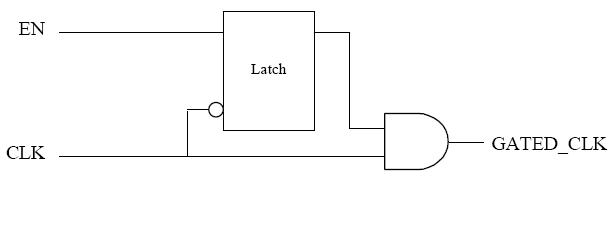
Clock gating (Dynamic)
Don't propagate the clock signal to idle sections of the fabric. This reduces dynamic power/energy as we reduce the amount of transistors switched in unused sections.
This can be done by inserting an AND-gate on the clock signal, enabled by an enable signal.
Power gating (Static)
This technique is based around using a single transistor for turning of
- Header switch (PMOS turning off access to power)
- Pros:
- Lower leakage for PMOS than NMOS
- Cons:
- Larger area than footer
- Pros:
- Footer switch (NMOS turning off access to ground)
- Pros:
- Smaller area than header
- Cons:
- Higher leakage for NMOS than PMOS
- Susceptible to ground noise
- Pros:
"Race to Halt" (Static)
Increasing the dynamic power consumption for a short duration so that we can complete the task faster and then enter low-power sleep mode (Using power gating), lowering the static power consumption. This works best for systems where the idle period between actions is comparatively long, or the static power consumption is a large portion of the total even when not idle. The idea behind this trade-off is of course to lower the total energy consumption.
Dynamic Voltage and Frequency Scaling (DVFS)
Lower voltage requires lower frequency
Production testing
The purpose of production testing is
Controllability & Observability
Controllabilty is how easily we are able to control the value of an internal signal, while observability is how easily we may observe the value of an internal signal. Both are concidered with only access to the circuits inputs and outputs.
Fault models
Faults come in either spot defects or distributed defects. Typical spot defects are short-circuits or open-circuits. There are two fault models discussed in this course: Stuck-at Fault Model Path-Delay Fault Model
Stuck-at Fault Model
This is the most widely used fault model. It tests if a signal is stuck at either 0 or 1. (S-A-0 or S-A-1) Because of this it models spot defects. It assumes that only one input on one gate will be faulty at a time.
Path-Delay Fault Model
Fault metrics
Fault Coverage
| Symbol | Meaning |
| Fault coverage | |
| # Modelled Faults | |
| # Detected Faults |
Defect Level
| Symbol | Meaning |
| Defect level | |
| Production yield | |
| Fault coverage |
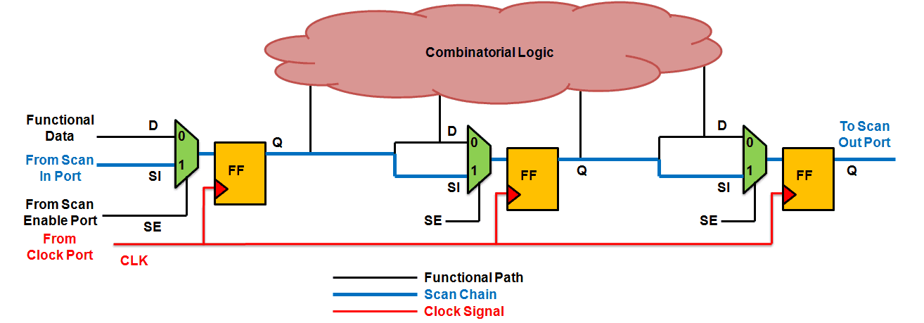
Scan chain
- Add logic for controllability and observability
- Add a mux on the input of a flip-flop to create a scan flip-flop. The mux has one
$scan_in$ input and a controll signal$scan_ctrl$ . The output of the flip-flop connects to$scan_out$ . - All the storage elements connected as a shift register.
Partitioning
D algorithm
$D = 1$ in the good circuit.$D = 0$ in the faulty circuit.$ \overline{D} = 0$ in the good circuit.$ \overline{D} = 1$ in the faulty circuit.- The idea is to code correct and faulty behaviour with an extended boolean alphabet: {
$𝑫,\overline{D} , 𝟎, 𝟏,𝑿$ }
Linear Feedback Shift Register (LFSR)
- Pseudo rabdom generator.
- Can be used to generate test signature.
RSA
| Symbol | Meaning |
| M | Plain text (Message) |
| C | Cipher text |
| e | Exponent (Public key) |
| d | Exponent (Private key) |
| n | Dividend (In Public key) |
Resources
Glossary
- Event: A signal changes value
- Transaction: