TTK4155: Embedded and Industrial Computer Systems Design
$$
\newcommand{\dt}{\,\mathrm{d}t}
\newcommand{\dx}{\,\mathrm{d}x}
\newcommand{\dy}{\,\mathrm{d}y}
\newcommand{\dh}{\,\mathrm{d}h}
\newcommand{\pt}{\partial t}
\newcommand{\px}{\partial x}
\newcommand{\py}{\partial y}
\newcommand{\QEDA}{\hfill\ensuremath{\blacksquare}}
\newcommand{\QEDB}{\hfill\ensuremath{\square}}
\newcommand{\R}{\mathbb{R}}
\newcommand{\Q}{\mathbb{Q}}
\newcommand{\bmat}[1]{\begin{bmatrix}#1\end{bmatrix}}
\renewcommand{\vec}[1]{\mathbf{#1}}
$$
# Embedded computer systems
### What is an embedded computer system?
An embedded computer is generally a part of a larger system, where the computer itself is not the main purpose. It is designed to to a specific tast, and is optimized to do so. The computer is programmable, but is not a general purpose computer like a PC, tablet or workstation.
### Peripherals
#### What is a peripheral?
A peripheral is some sort of device or computer hardware used to:
- Send data from the user to the computer
- Typically a computer mouse, buttons, touchpad, keyboard, webcam, scanner etc.
- Send data from the computer to the user
- Monitors, printers, speakers etc.
- Both of the above
- Touchscreens
- Store data
# Power supply
### Linear vs. Switching voltage regulators
Intergrated circuits rely on a steady power source to maintain its preformance. By using a voltage regulator it is possible to remove alot of ripple and noise from the source signal. Voltage regulators can be divided into two main categories: linear and switching.
#### Linear
* $-$ Poor thermal performance
* $-$ Power inefficient
* $+$ Can have low dropout voltage
* $+$ Cheap
#### Switching
* $+$ Power efficient
* $+$ Good thermal performance
* $-$ Expensive
### Linear voltage regulators
#### LDO
Low dropout regulator uses an amplifier and a transistor to regulate the voltage. When the output voltage differs from the desired reference the error is amplified, increasing the conductance of the transistor and increasing the voltage level on the output.

### Switching regulators
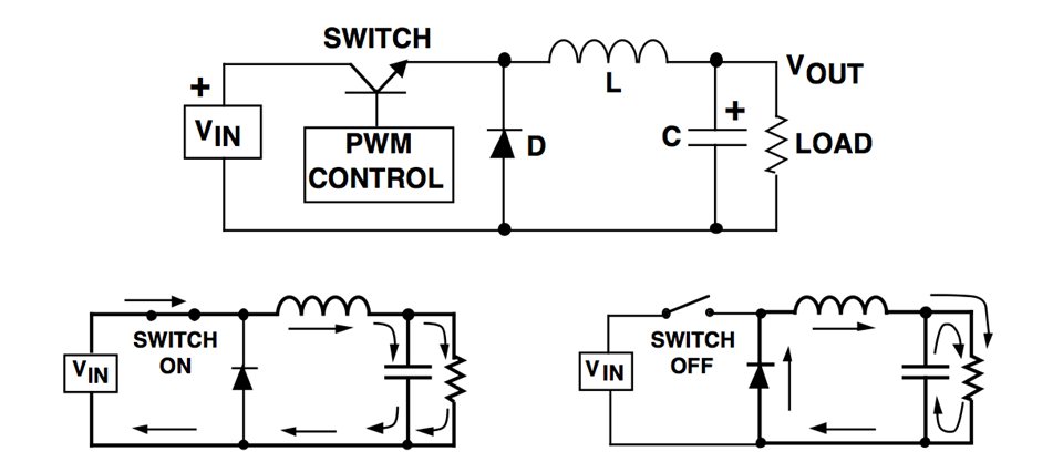
#### Buck regulator
Uses a transistor as a switch to connect and disconnect the input to an inductor. When the switch is on the inductor is charged up with current and when the switch is turned off the inductor supplies current to the load. A capacitor also contributes to smooth out eh load voltage.
## Microcontrollers
#### Interrupts
#### Polling
## Processor design
#### RISC - Reduced instruction set computing
RISC is a CPU design based on a very simple instruction set. The instructions are optimized for specific tasks, and is made so that each task of the instruction only takes one clock cycle for the processor to complete. The register set of a RISC processor is generally very large, because of the simplicity of each instruction.Generally like this:
1. Fetch
2. Decode
3. Execute
4. Memory access
5. Writeback
We see that the CPI (Cycles per instruction) of this sequence is 5, but this may of course be reduced down to 1 by pipelining(//Add ref//), and further reduced by adding additional execution-units. We generally see RISC preocessors have an CPI of 1-2.
RISC processors are very energy efficient and are therefore very popular in mobile devices. The downside of RISC processors is that they require a lot of coding by the programmer. Precise code may however lead to less complicated electrical components, and we may say that the RISC processor is software oriented (at least more software oriented than CISC).
#### CISC - Complex instruction set computing
CISC is looked upon as the "opposing" architecture to RISC. They have a very small instruction set compared to RISC, but thier instuctions are able to do a lot more. They are very popular due to their simplicity: one does not have to "Hard-code" everything. Due to this they are very much used in personal computers and workstations.
### Memory
### Memory access
### Address decoding
### Memory-mapped I/O
# Communications
## Serial communication
## Network
### CAN
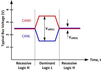
Controller Area Network is a bus standard developed by Bosch. It is wery robust and therefore used alot in projects where conditions of operation may vary. The network consists of two wires terminated at both ends by $120 \Omega$ resistors. One wire contain a low voltage signal ($0V-2,5 V$) and the other a
high voltage ($2,5V-5V$). Logic highs and lows are represented in as shown in the figure below.
#### Message frame
A CAN message data frame is a sequence of bytes and bits where different parts have different functions. At the start of the frame is the message ID, this is used by each node on the bus to determine what to do with the message. If the ID matches the nodes ID it can procede to decode the message. The CAN protocol is so that the message with the lower ID gets prioity on the buss. This is made possible by the dominace of the logic high's and low's.
After the message ID some controll bits are sent on the bus. Here is spesifies how many bytes of data the message contains. After this the data is transmitted in byte sized packs, up to a total of 8 bytes. The module then sends some CRC bits to check for errors before it ends the message with a series of high bits.

#### Error handling
## Wireless communication
# Analog-Digital interfaces
## ADCs
#### Successive approximation ADC
This type of ADC compares the input voltage to the comparison result and then updates the result depending on the comparison. A common way of SAR-logic is binary search.
For example, the input voltage is 6.3 V and the initial range is 0 to 16 V. The input 6.3 V is compared to 8 V (midpoint of the 0–16). Comparison gives less than 8 V, so the range is updated to 0–8 V. Second step, the input voltage is compared to 4 V. The comparison gives more than 4 V, so the range is updated to 4–8 V. FThird step, the input voltage is compared with 6 V. Comparison gives greater than 6 volts, and search range becomes 6–8 V. The steps are continued until the desired resolution is reached.
