IELS3012: Embedded Systems
Introduction
Previously, we have worked a lot with microcontrollers in embedded systems. We have worked with RTOS (Real Time Operating System), which allows us to create even more time-critical applications. Now it remains to dive into programmable circuits. We are working even more specifically with Field Programmable Gate Arrays (FPGAs). These are circuits where you can determine the hardware. PLA and PAL are examples of early programmable circuits that could implement simple combinational logic.
NB: Must not be confused with Application-Specific Integrated Circuits (ASICs), which are also designed using an HDL but cannot be changed after they are manufactured.
Why do we use programmable circuits?
Microcontrollers are cheap, quite flexible, can be designed to be very power-efficient, and are easy to use. Disadvantages of microcontrollers are that they are sequential and have limited processing speed. They rarely have the ability to handle large amounts of data and are made to be very general, which on one hand makes them versatile, but they cannot be used for more specialized applications.
Especially in systems such as video and audio processing (graphics), cryptography, and AI (matrix operations), it is important to design systems that are equipped to handle larger amounts of computation.
Programmable circuits are chips where the hardware can be programmed.
Advantages of these are that they are very flexible and suitable for a wide range of applications. They are fast and good for implementing parallelism. The disadvantages of these are that they are relatively expensive, more complex, and have higher power consumption.
How does an FPGA work?
In programmable circuits, one describes the interconnection of circuit elements to achieve a given behavior. In a system being designed, one explains the overall structure of the system, including the interface, and then describes each individual part of the system. One writes code that describes the system and synthesizes it. This means the code is interpreted and the given circuit elements are implemented. We then analyze whether the system provides the desired behavior in an iterative process.
This is most often done using Register Transfer Level (RTL), an abstraction level where we represent a system with combinational logic and flip-flops (registers).

A digital system has an interface, modules, and connections between these modules. They can be described by their interface (entity), their modules and behavior (architecture), and the interconnection between modules (structural). The design is built hierarchically so that each module in turn has its own interface and behavioral code or possibly interconnection of modules with their interfaces and behavioral code.

We use Hardware Description Languages (HDL) to describe electronic systems. It is not a programming language but a code language. This is because one does not create a program but rather describes the physical hardware. The most widespread HDL languages are VHDL and Verilog. We use VHDL in this course to describe digital systems. VHDL stands for VHSIC (Very High Speed Integrated Circuit) Hardware Description Language. VHDL is not case sensitive. VHDL is used for circuit synthesis (construction of circuits) and circuit simulation (testing of circuits). The first version of VHDL was VHDL 87. VHDL is used for, among other things, CPLDs (Complex Programmable Logic Devices) and FPGAs (Field Programmable Gate Arrays).
A typical logic element in an FPGA consists of: - a lookup table (LUT) - a register - a multiplexer for selecting between the previously mentioned units - an adder (usually)
Lookup Table (LUT)
The lookup table, LUT (LookUp Table), is used to implement logic functions, i.e., combinational circuits. An "LUT" (lookup table) is a lookup table that is a realization of a combinational expression where each word in the lookup table / memory specifies the output value, and the input values select the correct bit value using a multiplexer structure. It is generally the number of inputs (bits) that determines the number of LUTs for combinational circuits, not the complexity of the system.

Memory cells (RAM) are used to "store" the truth table of a logic function. The address of the memory represents the input values to the function.

VHDL
Coding Practices
A signal and variable are assigned as follows:
Signal: <=, e.g., sig <= 0;
Variable: :=, e.g., var := 0;
Code lines begin with --, block comments are written with /* */
Operators
- Highest precedence first, left to right within same precedence group, use parenthesis to control order.
- Unary operators take an operand on the right.
- "result same" means the result is the same as the right operand.
- Binary operators take an operand on the left and right.
- "result same" means the result is the same as the left operand.
** exponentiation, numeric ** integer, result numeric
abs absolute value, abs numeric, result numeric
not complement, not logic or boolean, result same
* multiplication, numeric * numeric, result numeric
/ division, numeric / numeric, result numeric
mod modulo, integer mod integer, result integer
rem remainder, integer rem integer, result integer
+ unary plus, + numeric, result numeric
- unary minus, - numeric, result numeric
+ addition, numeric + numeric, result numeric
- subtraction, numeric - numeric, result numeric
& concatenation, array or element & array or element, result array
sll shift left logical, logical array sll integer, result same
srl shift right logical, logical array srl integer, result same
sla shift left arithmetic, logical array sla integer, result same
sra shift right arithmetic, logical array sra integer, result same
rol rotate left, logical array rol integer, result same
ror rotate right, logical array ror integer, result same
= test for equality, result is boolean
/= test for inequality, result is boolean
< test for less than, result is boolean
<= test for less than or equal, result is boolean
> test for greater than, result is boolean
>= test for greater than or equal, result is boolean
and logical and, logical array or boolean, result is same
or logical or, logical array or boolean, result is same
nand logical complement of and, logical array or boolean, result is same
nor logical complement of or, logical array or boolean, result is same
xor logical exclusive or, logical array or boolean, result is same
xnor logical complement of exclusive or, logical array or boolean, result is same
Taken from University of Maryland. Another useful source.
Naming Conventions
Names for signals, variables, entities, packages, etc., have a set of rules for how they can be written.
- Can contain letters between a-z (A-Z), digits (0-9)
- Must start with a letter
- Must be different from reserved words
- Cannot contain two or more underscores next to each other and cannot end with an underscore ("__")
Design Flow in VHDL
-
Analysis and processing: The code is checked for errors and creates an RTL-level representation
-
Simulation: Test that the circuit behaves as it should
-
Synthesis: Translation to circuit representation
-
Place and Route (P&R): Implementation, the circuit is adapted to the device to be used (De10-Lite)
-
Timing analysis
-
Programming
-
Test on hardware (HW)
Structure of a VHDL Design

Illustration showing a VHDL design divided into packages, interface (entity), and circuit description (architecture).
Entity
entity ports: IN, OUT, INOUT (bidirectional) or BUFFER, if you want to use the signal internally in the code

Generic
Can help provide better organization in the code, make the code more readable and reusable.
The value for a generic will be the one specified in the generic map initialization, i.e., 4 ns if this is not specified, the generic in the Component declaration will be used (2ns), and if this is also not defined, the generic in the entity is used (3ns)
Which value for gc_gate_delay will be used for the XOR gate? Justify your answer.
entity xor2 is
generic (gc_gate_delay : time := 3 ns);
port (
In1, In2 : in std_logic;
z : out std_logic);
end entity xor2;
architecture behavioural of xor2 is
begin
z <= (In1 xor In2) after gc_gate_delay;
end architecture behavioural;
architecture structural of half_adder is
component xor2 is
generic (gc_gate_delay : time := 2 ns);
port (
In1, In2 : in std_logic;
z : out std_logic);
begin
i_xor2 : xor2
generic map (gc_gate_delay => 4 ns)
port map (
In1 => x, In2 => y, z => sum);
end architecture structural;
Architecture
The purpose of an "architecture" in VHDL is to describe the internal implementation of a component.

Concurrent versus Sequential Statements
An important principle in hardware description languages, including VHDL, is concurrency. - In digital circuits, everything happens simultaneously. - This is reflected in VHDL by allowing statements to be written in any order. - But a given signal can only be assigned a value once. - Exception: Certain code structures (processes and subprograms) are interpreted line by line but are always concurrent in relation to the rest of the code.
Processes are concurrent with respect to all other statements, but internally a process is sequential (only statements in (b)). Statements are inherently concurrent (parallel)sequential inside PROCESS, FUNCTION or PROCEDURE.


Select (concurrent)
Example: multiplexer, where sel is of type natural.
with sel select
y <= a when 0,
b when 1,
c when 2,
d when others;
There is also the matching select statement select? which uses the matching equality operator ?=, which is useful when you have a truth table that includes "don't care" values.
When (concurrent)
target <= value when condition else
value when condition else
value;
- has priority encoding (for truth tables use select)
- ends with else, guaranteeing no latch.
Example with multi-bit tri-state buffer):
outp <= inp when ena = '1' else
(others => 'Z');
Generate (concurrent)
- for-generate (most used)
- if-generate
- case-generate.
- For-generate: Acts as a loop where a piece of hardware is inferred for every iteration.


Process (sequential)
- Internally sequential (mini program).
- Each process is concurrent with respect to all other statements.
- Must be used when constructing sequential circuits, but can also be used for combinatorial circuits.
- Procedures and functions are sequential
- Sequential statements allowed in processes:
- If (sequential version of when)
- Case (sequential version of select)
- Loop (sequential version of generate)
- Wait
If (sequential)
The sequential version of when, which is concurrent. - has priority encoding - All combinations must be covered to avoid latches in combinational logic. - No action on if-statement -> unaffected or null
Case (sequential)
The sequential version of select, which is concurrent.
- Used mostly to implement a truth table
- Has no priority encoding (compared to if)
- No action on case statement -> unaffected or null
[label:] case expression is
when choice => assignments;
when choice => assignments;
when others => assignments;
end case;
Loop (sequential)
The sequential version of generate, which is concurrent.
- Can only be used in processes and subprograms
- loop (unconditional, simulation only)
- while-loop (simulation only)
- for-loop (most frequently used for synthesis)
- loop with exit
- loop with next
- For synthesis: The range must have static bounds.
Object Classes in VHDL
An object is an entity that has a value of a data type. There are four object classes in VHDL. • Constant: Only readable, cannot be changed. • Signal: Used for signaling between processes. • Variable: Only for internal use in a process, procedure or function. • File: Only used in testbenches (not hardware).
Signal
- Capable of passing values in and out of the circuit or between internal parts (wires).
- Declared (created) in the declaration part of entity, architecture, package, generate or block.
signal signal_name: signal_type [:= default_value];
Remark: Default value for signals should be avoided in code for synthesis (reset-signal should be used to initialise registered signals).
Variable
- Only used in sequential code.
- Declared (created) in processes and functions/procedures.
- Updated immediately.
- Initial value optional, but more meaningful than for signals.
- Do not use shared variable (use signals instead).
variable variable_name: variable_type [:= initial_value];
variable count: natural range 0 to 2**NUM_BITS-1;
count := count + 1;
Signal versus variable
Signals can be declared in an architecture (between architecture and begin), while variables must be declared in a process (between process and begin or locally in a function/procedure) (shared variables can be declared as signals). For assignment of signals, <= is used, and for variables, := is used. Signals are updated after a process has run, i.e., they use the old value in the process where a new value was assigned. Variables are updated immediately, i.e., the new value is used after the new value has been assigned. Signals do not change value until the entire process has run and can be used between processes/globally. Variables change value immediately and can only be used locally in a process and cannot be returned.

Data Types
- VHDL: Strongly typed language.
- Does not allow data transfer between objects of different types (even if they are identically declared).
- Appropriate casting functions must be used.
- Does not allow implicit type conversion.
- Every operator is constructed for specific data types.
- Types can be predefined or user-defined.
- It is allowed to define your own data types in VHDL
- It is not possible to define signals with the type real during hardware synthesis
- The data type bits defined by '0' and '1'. Note that
std_logichas multiple definitions. - Boolean → 1 bit
- Integer → 64 bit/32 bit
Classes of Data Types
- Scalar (integers, enumeration types, floating point, physical)
- Composite (array/record)
- Access (simulation only)
- File (simulation only)
- Protected (simulation only)
std_logic
Two important data types to note are std_logic and std_ulogic. Both can represent the following values:
| Value | Explanation |
| ‘1’ | Logical 1 |
| ‘0’ | Logical 0 |
| ‘Z’ | High impedance |
| ‘W’ | Weak signal, unknown |
| ‘L’ | Weak 0, pulldown |
| ‘H’ | Weak 1, pullup |
| ‘-‘ | Don’t care |
| ‘U’ | Uninitialized |
| ‘X’ | Unknown, multiple drivers |
Read more about differences and similarities between std_logic and std_ulogic on VHDLWhiz's page about these data types.
Aggregation and Concatenation
- Putting data pieces together to form or enlarge data arrays.
signal s1, s2, s3, s4: std_logic_vector(3 downto 0);
s1 <= ('1','0','1','0') -- Aggregation: s1="1010"
s2 <= ('1','0',others => 'Z'); -- Aggregation: s2="10ZZ"
s3 <= "11" & "00"; -- Concatenation: s3="1100"
s4 <= '1' & s3(3 downto 1); -- Concatenation: s3="1110"
Subprograms
Function
- Will always return a single object of a specified data type calculated based on a given set of input parameters.
- Will always create combinatorial logic.
- Can be:
- Pure: does not rely on external objects and will always yield same results with same parameters.
- Impure: can access external objects and give different results with the same parameters.

- Name: Must follow the rules for VHDL identifiers.
- Input list: Can contain any number of parameters.
- They can have the classes constant (default), signal or file (variable is not allowed).
- Always returns one object, return type must be specified.
- Must always be part of a complete expression.
- Declarative part: Typically for internal variables.
- Statements: Only sequential (as in process), but no support for wait.
- Synthesis of function → combinational logic
Pure function: - Always returns the same result for the same parameters. - Does not depend on external objects (signals or variables). Impure function: - Can return different results even with the same parameters. - Can access external objects (e.g., files). - Not recommended for synthesis.
Procedure
- Main difference from functions: Can have multiple output values
- Can handle time (wait statements).
- Can read from/write to files (useful in testbenches/simulation).
-
For synthesis: More common to use functions than procedures
-
Name: Must follow the rules for VHDL identifiers.
- Input/output list: Can contain objects of all classes (constant, signal, variable, file).
- in: constant (default), signal, variable.
- out/inout: signal, variable (default).
- Files have no mode.
- The object class applies only locally in the procedure, not in the calling unit.
- Can handle time
- Useful in testbenches.
- Standalone statements
- Is not part of an expression.
Differences and Similarities Between Functions and Procedures
| Property | Function | Procedure |
| Use cases | Simplify common operations, repetitive code | Solutions requiring multiple output values(simulation) |
| Input/output | Unlimited input, one output | Unlimited input and output, including bidirectional |
| Support for time | No support for time(wait) | Support for wait and fil |
| Call | Called as part of an expression | Called as a standalone statement |
| Subprogram call | In both concurrent and sequential code | In both concurrent and sequential code |
Packages
- Collection of functions/procedures.
- As well as types/constants.
- "package" is a collection of related functions, procedures and decorations.
- library → collection of FUNCTIONS, PROCEDURES and COMPONENTS in PACKAGES.
LIBRARY ieee;
USE ieee-std-logic-1164.all;
- Collection of declarations (for example functions and procedures) that are common for a model.
- Can be predefined or user-defined.
use ieee.numeric_std.all;is for example predefined. Purpose:- Avoid writing the same code over and over again.
- Better organization and simpler code.
- Can be reused in other projects. Packages consist of:
- Package declaration
- Package content (the contents)
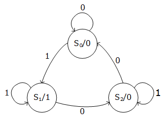
State Machines
A state machine can be described as a case statement in a combinatorial process. One can also implement state machines as a clocked process.
Moore
In Moore state machines, the output of the state machine is only dependent on the current state of the state machine. Input only affects transitions between different states.
Mealy
In Mealy state machines, the output is dependent on both the current state and the input. (Output changes with transitions between states, not the state itself.)
Main Differences Between Moore and Mealy
| Property | Moore | Mealy |
| Outputs depend on | Current state | Current state and input value |
| Output changes at | States | Transitions |
| mber of states | Often more | Often fewer |
| sponse time | Slower (output after state) | Faster (output during transition) |
| Complexity | Simpler output logic | Slightly more complex output logic |
(Taken from Scott Davis (2025))
Examples of State Machines (Clocked and Combinatorial)
The entity and architecture can be declared similarly. In the architecture, one defines a custom type for the different states, and uses a signal to store the state value.


Clocked Process
- Triggered on reset and rising clock edge.
- Stores the next state value.

Combinatorial Process
- Calculates the next state based on the current state.

Testbenches
Testbenches are VHDL code that verifies that the circuit implementation (DUV/DUT (Device under Verification/Test)) described by VHDL code has the desired behavior.


The tasks of a testbench are as follows:
- Create stimuli on the input of the system (DUV/DUT)
- Compare the response from DUV/DUT with the expected result
- Report the results from the verification process.
One can test with a functional simulation, which is without delays, or with a timing simulation which includes propagation delay. It is possible to do simulation both with and without the internal time delays in an FPGA circuit.
Assert
- Main purpose: Checking the design.
- Used in testbenches.
- Does not infer any hardware.
- Can be used in both sequential and combinatorial code.
- The message (static and/or dynamic) is displayed when the condition is false.
[label:] assert condition [report message] [severity level];
Severity Level
- An assert can have different levels of severity:
- Note: For information sharing
- Warning: Something abnormal was detected.
- Error: An error is detected (default level)
- Failure: A bug in the code.
- At failure, the simulation stops, so this can be used to end the testbench:
- It is you as the designer and tester who specifies the severity level. assert false report "Testbench finished" severity failure;
Note: In VHDL 2008 one can also use finish as a command to end the testbench, but I don't think this is mentioned in the curriculum.
It is often desirable to have dynamic values in the report part of the assert. Then to_string can be used to convert number values to a string. Strings can be concatenated with &.
assert actual_value = expected_value
report "Actual value does not match expected value at t=" & to_string(now) & "."
severity error;
Note: Reading and writing to file and textio are not covered in this compendium as it is considered less relevant for the exam, and is more like extra supplementary knowledge.

In this example, "This is a test… Value = 10 meters" will be written to the file out.txt. To write to the console instead of a file: writeline(output, v_buf);
Dealing with Time in VHDL
-
Major difference between code for synthesis and simulation: The presence of time in the latter.
-
Useful constructions for testbenches related to time:
-
wait forThe process waits for a specific time. -
afterAn action is scheduled after a specific time. -
nowReturns the current simulation time. -
S'stable(t)Attribute, returns true if no events have occurred on signal S during the last t time units (looks backwards). -
S'last_eventAttribute, returns the time since last event on S.
-S'transaction Attribute, causes a bit to toggle when a transaction (future event) on signal S is scheduled.

Examples of Simple Expressions

The system described in wait expressions:
p_test1: process is
begin
test1 <= '1';
wait for 20 ns;
test1 <= '0';
wait for 10 ns;
end process p_test1;
p_test2: process is
begin
test2 <= '0';
wait for 30 ns;
test2 <= '1 ';
wait;
end process p_test2;
Good to Know
Sequential Logic versus Combinatorial Logic
Digital logic has two main categories; combinatorial logic, where changes happen immediately, and clocked logic, where changes happen at a clock edge. Clocked logic is also called sequential logic. The difference between clocked logic and combinatorial logic is that clocked logic contains memory in the form of flip-flops, thus it is not necessary in the code to assign all signals every time, as in combinatorial logic. Clocked logic is dependent on the system's previous values/states. Clocked logic is built up of flip-flops, which update outputs on each edge of a clock signal. Combinatorial logic is realized with logic gates. Combinatorial logic requires no knowledge of the system's previous state, while sequential logic is dependent on knowing the system's previous state.
Latches and Flip-Flops
- Latches and flip-flops are "registers". They are units for storing information.
- Latches → level-sensitive, transparent when clk is high, opaque when clk is low.
- Flip-flops → edge-sensitive, transparent at clock transitions
If one wants a combinatorial circuit without a latch, one must ensure that variables are always assigned a value in or before an if-statement, or include an "else" in the code. If a variable is used before it is assigned in the process, one must add a register element to remember the previous value of the variable. Make a table to check if all signals in an if-loop are assigned a value!
- A signal must always be assigned a value in concurrent processes or else latches will be inferred (combinatorial loops).
- Make sure to use others and remember that
std_logichas more possible values than ‘0’ and ‘1’. - We don’t want latches.
- If using the if statement in a process all combinations must be covered for concurrent logic.
- Not necessary for sequential logic.
- Do not use unaffected in combinatoric logic → Latches
A Bit About Metastability and Glitches
- Metastability → when data changes in the forbidden time interval (flip-flops)
- Requirement: Data-signal must be stable a time tsetup before the clock edge and a time thold after the clock edge.
- Metastability (undefined voltage or illegal digital state) can occur if the timing requirements are violated.
- Use two-flop synchronizer to avoid metastability: The synchronizer introduces extra latency.
- Glitches → caused by propagation delays
- A glitch can occur in a combinatoric circuit when there is a race between two (or more) signal paths.
- In a synchronized system: Glitches can only occur immediately after the clock transitions (usually not a problem as long as the output is not used as a clock).
- Avoid glitches: Use different clock edges, synchronize the outputs from a combinatorial circuit with flip-flops.
Sensitivity Lists and Wait Expressions
A sensitivity list is a listing of the signals that the process should react to. The process runs when there is a change in the signals in the sensitivity list. In e.g., Quartus Prime Lite, the synthesis can recognize missing signals in the sensitivity list and add them, while in a simulation this will create errors. This is something one must be aware of when getting a task that describes a system that behaves differently in synthesis versus simulation.
wait: The process waits for the wait condition to be fulfilled, and must therefore be the first instruction/command in the process. With sensitivity lists, one can create a combination of combinatorial and clocked logic. This cannot be done with wait expressions.
When there is a change (event) on at least one signal in the sensitivity list: - The process is executed. - Once started, the process runs to completion (to the end process statement).
An alternative to sensitivity list: - Use a wait statement (responsible for starting the execution of the process), must be the first statement if writing code for synthesis. - The process runs to completion, and stops at the wait statement (process suspends until the wait statement again is true).


Hexadecimal
Hexadecimal is a number system that contains 16 different ways to represent numbers, 0, 1, 2, 3, 4, 5, 6, 7, 8, 9, A, B, C, D, E, F. This is called a base-16 system.
Decimal 15 is thus described as hexadecimal F. When describing e.g., 16 or 17, one starts over in the hexadecimal sequence, with 10 (decimal 16) and 11 (decimal 17).
Decimal 15 can be described as '1111' in binary, and this makes hexadecimal used as a method to shorten expressions in binary. This is widely used to analyze signals to save space and write shorter code.
In VHDL, one can write a hexadecimal number as X"AD", which is equal to the more common naming convention in C, 0xAD.
Decoding hexadecimal to binary was an exam question from an earlier similar subject, and the way to do it is as follows:
One splits the number "AD" into its parts, A and D. These can then be used to convert to decimal numbers, 10 and 13. Representing 10 in binary gives 1010 (8 + 2), and representing 13 in binary gives 1101 (8 + 4 +1). This can then be put together as "10101101", which is the binary number.
Description of a System
When describing a system, remember clock and reset. Think about overflow/underflow! When describing an entity from an interface, be aware of the number of bits on each signal.
Detect Clock Edges
- Both work for synthesis, but the rising_edge/falling_edge are recommended because:
- Checks the value before and after the clock transition.
- Works also for 'L' and 'H' values (converted to '0' and '1').
- Works also for data types bit and boolean.
if clk'event and clk = '1' then … -- Positive clock transition
if clk'event and clk = '0' then … -- Negative clock transition
if rising_edge(clk) then … -- Positive clock transition (recommended)
if falling_edge(clk) then … -- Negative clock transition (recommended)
Avoid Multiple Assignments to a Signal
- Not allowed to assign a value to a signal from several places.
- Concurrent code: Only possible to assign a signal one place, or inside one combinatoric process.
- Sequential code: A signal can be assigned several times, but only inside the same process.
Suggested Procedure for Arithmetic Circuits
-
- If the circuit is arithmetic: Integer or floating point?
- Floating point should be avoided in VHDL due to higher usage of resources, higher power consumption and lower speed.
-
- List all operations involved (+, -,
*, /,**, rem, mod, abs) and check the constraints for each operator to be used:
- List all operations involved (+, -,
- Types (unsigned or signed).
- Number of bits in the result.
-
- How to deal with overflow:
- Extend the operands. •-Flag (must decide how to handle a flag).
Arithmetic Circuits in the VHDL code
-
Use only standard-logic data types for the circuit ports.
-
In the architecture: Convert the standard-logic vector to one of the arithmetic data types.
-
Do the computations.
-
Convert the results back to standard-logic vector on the ports.
-
Carefully simulate the design.
Component Instantiation Statements
- Declaration of the component (identical with the entity).
component component_name [is]
[generic (…);]
port (…);
end component [component_name];
- A component instantiation statement.
label: [component] component_name
[generic map (generic_association_list)]
port map (port_association_list);
Other Notes
In this compendium, sequential vs concurrent and combinatorial vs clocked logic are used somewhat interchangeably.
Concurrent and sequential code describe how VHDL code runs, while combinatorial and sequential logic describe the behavior of the hardware that the code describes. This is not given very consistently in the text, so be aware of this.
This page was translated by Kagi translate.
Exam Tips
- Practice previous exams, go through exercises and ERT sessions and do tasks from the book.